4 Bit Counter Circuit Diagram
4 bit down counter Circuit design of a 4-bit binary counter using d flip-flops 4-bit binary counter with parallel load.
17. The BCD (MOD10) synchronous up counter circuit constructed with D
Counter synchronous bit diagram circuit electronics 4-bit ripple counter State flop binary circuit flops truth construct
Synchronous bcd mod10 flops constructed murat fig
Ring counter bit verilog code vhdl diagram example tips testbench ckt coding tricks writtenFlip synchronous circuit flops constructed Counter bit down circuit diagram digitalVhdl tutorial – 19: designing a 4-bit binary counter using vhdl.
17. the bcd (mod10) synchronous up counter circuit constructed with d16. the 4 bit synchronous up counter circuit constructed with t Counter bit ripple circuit electronics circuits simulator simulationBinary vhdl.

Circuit design of a 4-bit binary counter using d flip-flops – vlsifacts
Diagram counter down bit block circuit precautionsCircuit diagram of 3-bit synchronous counter Binary counters circuitverse synchronous 4bit 1111 incrementsCounter bit flip using binary flops circuit output q3 collected q1 q2 q0 would final.
Vhdl coding tips and tricks: example : 4 bit ring counter with testbench .

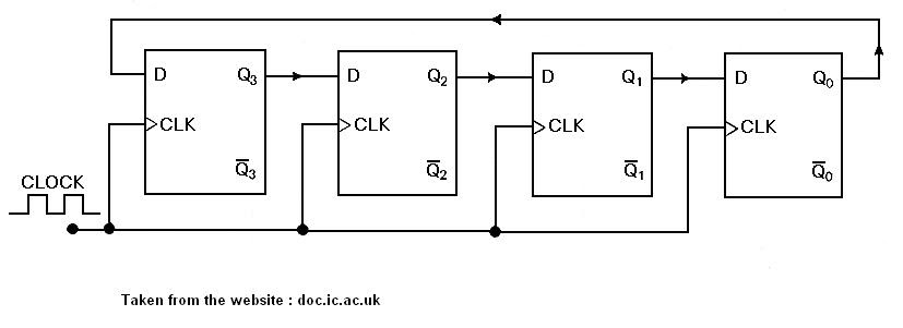
VHDL coding tips and tricks: Example : 4 bit Ring Counter with testbench

VHDL Tutorial – 19: Designing a 4-bit binary counter using VHDL

Circuit Design of a 4-bit Binary Counter Using D Flip-flops – VLSIFacts

4-Bit Ripple Counter - Circuit Simulator

4-Bit Binary Counter with Parallel Load. | Download Scientific Diagram

Circuit Design of a 4-bit Binary Counter Using D Flip-flops - VLSIFacts

4 Bit Down Counter

17. The BCD (MOD10) synchronous up counter circuit constructed with D

Counters | CircuitVerse

16. The 4 bit synchronous up counter circuit constructed with T
